
3.5.1.1 Basics of electricity
Electric current as the rate of flow of charge; potential difference as work done per unit charge.
$I=\frac{ΔQ}{Δt}$, $V=\frac{W}{Q}$
Resistance defined as $R=\frac{V}{I}$
Intro
In the modern world, electrical circuits are ubiquitous. Almost every aspect of our lives involve electronic circuitry with varying degrees of complexity. It can, however, be hard to understand what is going on within some of the components and how the current behaves. This module looks at understanding the behaviour of simple resistive circuits, and the electrical properties of conductors.
Circuit symbols
The majority of the components that you will use in this module of A level are the same as the ones that you have used before, but it is worth reminding ourselves of their symbols and their functions.
| Component | Symbol | Function |
|---|---|---|
| Cell |  |
A cell provides the energy for a circuit, or the emf. |
| Battery | 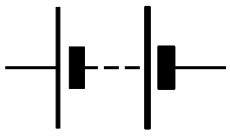 |
A battery is several cells joined together, although, generally, the two terms are interchangeable, and many shop bought batteries, are just that. |
| Resistor | 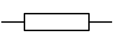 |
These components reduce the current. They can be used to control the flow of charge and are the basic building block for many circuits. |
| Variable resistor | 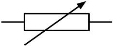 |
A resistor, whose value can bu manually altered. |
| Thermistor | 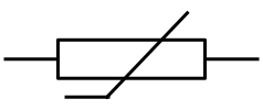 |
A resistor, whose value can be altered due to the external temperature. These components are intrinsic semiconductors. |
| Filament bulb |  |
Also known as an incandescent bulb. The convert electrical energy into light and (mostly) heat. |
| Light emitting diode (LED) |  |
A much more efficient light source. These are also semiconductors, and waste very little energy in the production of light. |
| Ammeter |  |
This measures the electrical current. They are always set-up in series within a circuit |
| Voltmeter |  |
This measures the potential difference or voltage across a component. They are always set-up in parallel. |
Current and charge
At the most fundamental level, all matter is electrical. Everything is made from small charged particles, charge is a property of matter, and it is the movement of charge that gives rise to electricity. In any electrical circuit charge is moved; in most cases the moving charges are free electrons in the metal conductors, but they could also be free ions in a liquid or a gas. The flow of charge is an electric current. If more charge flows then the current increases.
Charge is measured in coulombs (C), and the basic charge carrying unit, the electron, has a charge of $\quantity{1.60\times 10^{-19}}{C}$. We would therefore require $\frac{1}{\quantity{1.60\times 10^{19}}{C}}=6.24\times 10^{18}$ electrons to make up a single coulomb of charge.
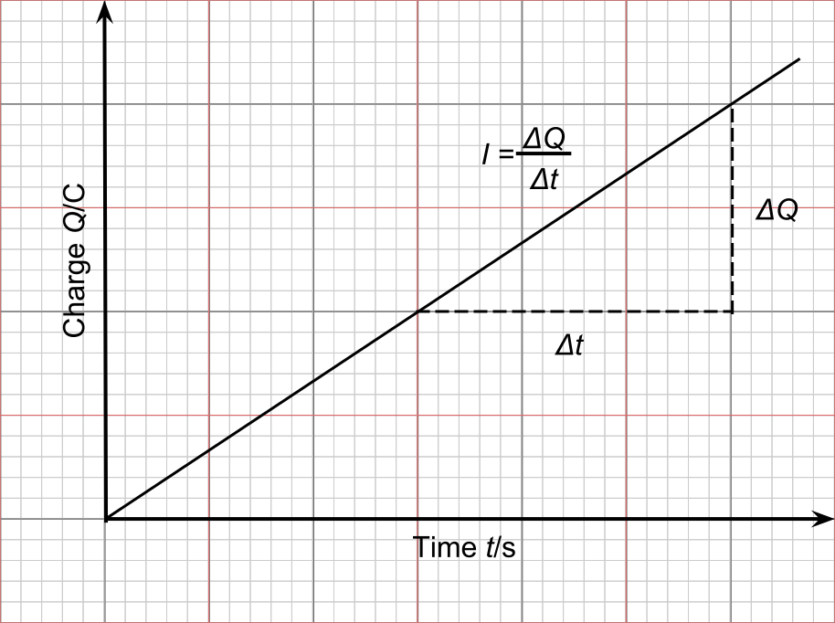
Current is defined as the rate of flow of charge, and can be thought of as the amount of charge that passes a point in a circuit per unit of time, It is defined by the equation:
Where:
- I is the current in amps
- ΔQ is the charge in coulombs
- Δt is the time in seconds
It is important to note that it is the change in charge, $\Delta Q$ in time $\Delta t$, not the total charge. This is because the current is the charge that has moved past a point (an ammeter) for example, in time t. This would be the equivalent of finding the current by finding the gradient of charge-time graph.
If, for example we have a circuit with a current of $\quantity{10.0}{mA}$ flowing for one minute we can calculate the total charge that flows through that circuit:
Looking at the calculation above it can be seen that electrical charge is the product of current and time. Many modern batteries that store a lot of charge and the coulomb is not always the most appropriate unit. Many mobile phones advertise their batteries using the non-SI unit called the milliamp-hour ($\quantity{}{mAh}$). A top of the range phone may have a battery which can store a charge of $\quantity{3000}{mAh}$ which means it can deliver a continuous current of $\quantity{3000}{mA}$ or $\quantity{3}{A}$ for 1 hour or $\quantity{3}{mA}$ for 1000 hours. This charge is equivalent to:
Conventional current
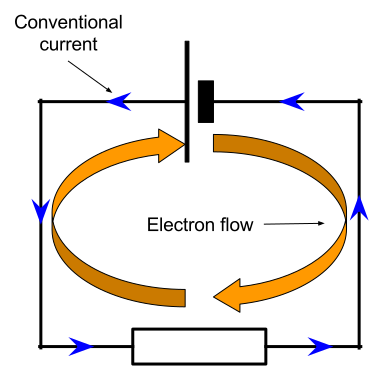
As current is the flow of charge, and in most electrical circuits the charge carriers are electrons which have a negative charge the charge in fact moves from the negative terminal to the positive terminal of the cell or power supply. However, conventional current flows from positive to negative. This is as a result of the historical convention of defining the electron as having a negative charge. Whenever the word current is used, it will be in terms of conventional current, but whenever the word charge is used it will be in terms of the charge of the actual particles in question.
Current in circuits
The amount of current that flows in a circuit depends on the resistance of that circuit and the emf (or voltage) of the the power supply. The greater the resistance, the lower the current that can flow through the circuit, the greater the voltage of the power supply, the greater the current for a fixed value of resistance. Current is measured with an ammeter which is set up series within a circuit. An ammeter must have a very low resistance, approximately zero, otherwise it would affect the amount of current flowing within the circuit.
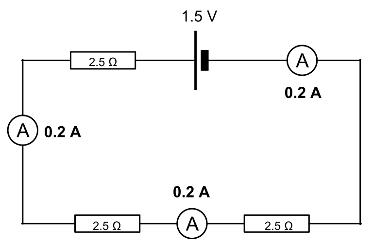
A very important, but easily forgotten, rule is that the current around a circuit is constant. This is easy to spot in a simple series circuit as below where each ammeter has the same reading, demonstrating the constant current. It is also important to note that the current displayed on the ammeters is the same as the current flowing through the cell itself.
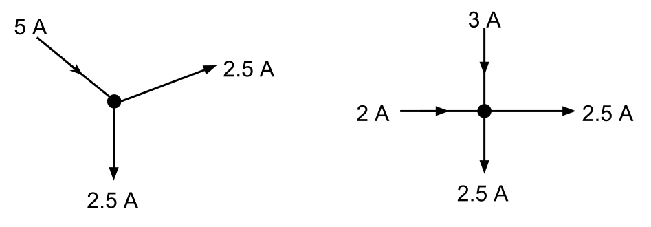
It is a little harder to see that this still holds true for parallel circuits, so it may be easier to remember that the current leaving the cell is the same as the current returning to the cell. In a parallel circuit, the current splits at the junctions with the current in each branch depending on the resistance of that branch, but all the current will return to the cell. This is known as Kirchhoff’s 1st law, which states that, the current entering a junction is equal to the current leaving the junction.
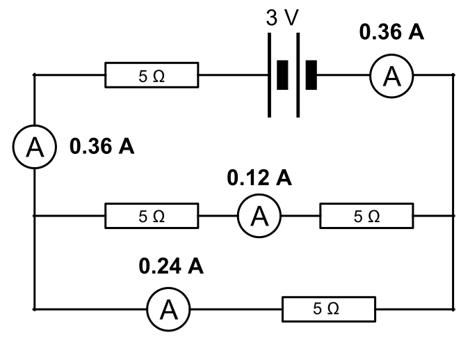
In practice this means that in a parallel circuit, branches with higher resistance will have a lower current flowing through them, but the sum of all the currents flowing in all of the branches will equal the current flowing through the whole circuit. If we know the total current and the current in one branch we can calculate the current in the other branch.
In exam questions, you may not be given quite as much information and you will have to calculate the currents from other given values. We will explain how to do this in another section.
Potential difference
As it moves around the circuit, the charge carries potential energy which it can convert to useful work. Although charges are always moving around a circuit when current is flowing, they are not always using up their potential energy. This electrical potential is only used when the charge passes through a resistance. When a current flows through a resistance the electrical potential is converted to heat, or light, or kinetic energy. Electric current effectively moves energy from store (a cell for example) to another (heat in a room)
The amount of work done by a unit of charge as it passes through a resistance is called the potential difference. This is what is often referred to as the voltage across a component. Potential difference is defined as:
Where:
- V is the potential difference in volts
- W is the work done in joules
- Q is the charge in coulombs
Potential difference is measured using a voltmeter which is placed in parallel across a component. It must have a very high resistance, nearly infinite, to prevent any current flowing through it.
The battery, or power supply, provides all of the energy to the charge, which is then used up around the circuit, so that the charges returning to the battery, or power supply will have an electrical potential of $\quantity{0}{V}$. This does not mean that the charges have no energy at all, but their potential is zero compared to the gain in potential that the charges recieve inside the cell or power supply. The charges will only lose electrical potential when they pass through a component, the greater the resistance of the component, the greater the loss of potential, and the greater the potential difference across that component. This is analogous to gaining gravitational potential energy by cycling up a hill. That gravitational potential energy can be converted back into useful work as you descend the hill to kinetic energy. You only lose gravitational potential energy when you are descending, so if the bike coasts along a flat section of the hill you will continue to move forward, but your gravitational potential energy will not change. When you get to the bottom of the hill the total change in gravitational potential energy is equal to the gravitational potential energy gained by the initial climb. This can be represented by the hill diagram below.
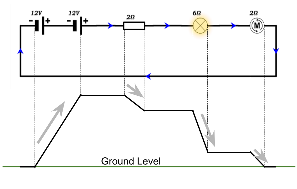
As the charges pass through the cell they gain energy, so unlike potential difference where the charges do work as they pass through a resistance, in the cell work is done on the charges which gives them more potential. This is equivalent to going to the top of the hill to gain gravitational potential energy in our analogy. The energy gained per unit of charge is called the emf (short for electromotive force, but as it is not a force we will always use the abbreviation). The units for emf are volts as it is defined as:
Where:
- ε is the emf in volts
- E is the energy supplied in joules
- Q is the charge in coulombs
This definition is very similar to that for potential difference, and the only difference that you need to remember is that the emf gives charges energy, but the when there is a potential difference the charges lose energy.
The emf of the cell is used up around the circuit as the current passes through the resistances. So the sum of the potential differences across all of the components in the circuit is equal to the emf supplied to the circuit. This is known as Kirchhoff's 2nd law and can be applied to series circuits and parallel circuits.
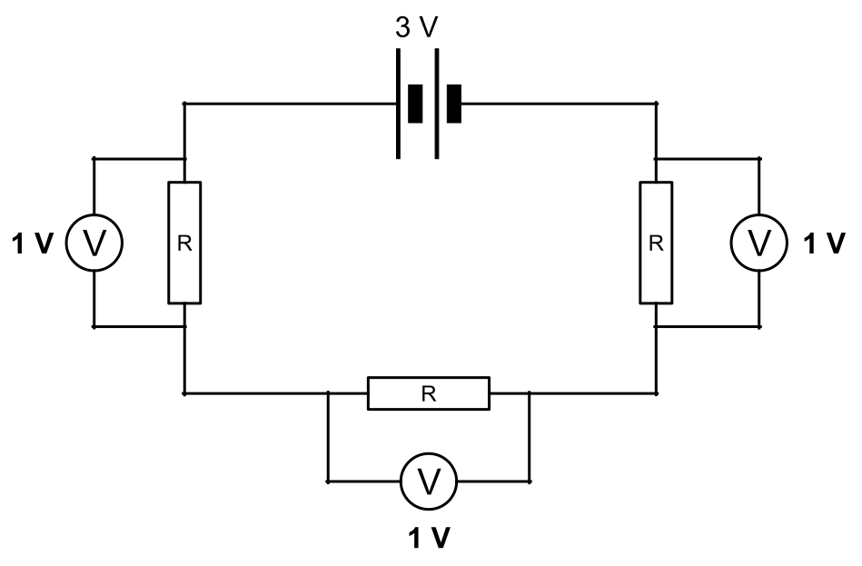
In the circuit above the values of the resistors is marked as R. It does not matter what their actual values are, as they all have the same resistance, so will have the same p.d. across them. If the emf supplied to the circuit was higher, each resistor would have to dissipate more energy and the p.d. across each would be greater.
In parallel circuits, to understand that the same law applies we need to think about the loops the current makes around the circuit. The total potential difference around each loop will equal the emf of that loop.

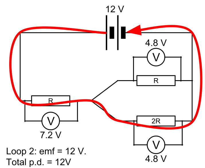
Even though each loop has a different resistance the total potential difference around each is the same, and importantly, the p.d. across the two branches is also the same.
Worked example
This question was in the specimen paper for the new A level specification, but it neatly demonstrates some of the ideas we have looked at on this page.
The cells in the circuit shown in the figure below have zero internal resistance. Currents are in the directions shown by the arrows.

$R_{1}$ is a variable resistor with a resistance that varies between $\quantity{0}{Ω}$ and $\quantity{10}{Ω}$.
- Write down the relationship between currents $I_{1}$,$I_{2}$ and $I_{3}$
- $R_{1}$ is adjusted until it has a value of $\quantity{0}{Ω}$ State the potential difference across $R_{3}$.
- Determine the current $I_{2}$.
- State and explain what happens to the potential difference across $R_{2}$ as the resistance of $R_{1}$ is gradually increased from zero.
This question is asking about the three current around the junction, so it is an application of Kirchhoff’s 1st law. The current leaving the junction, $I_{3}$, is equal to the sum of the currents entering the junction, $I_{1}+I_{2}$. So the answer can be stated as:
This question looks trickier than it is because we have two power supplies and a shared resistor in the centre, so will the p.d. across the resistor be a combination of both of these cells?
Well if we apply the ideas of loops from Kirchhoff’s 2nd law we can solve this easily. The variable resistor is now set to a value of $\quantity{0}{Ω}$ so we can redraw the circuit as below and imagine the two loops around it.
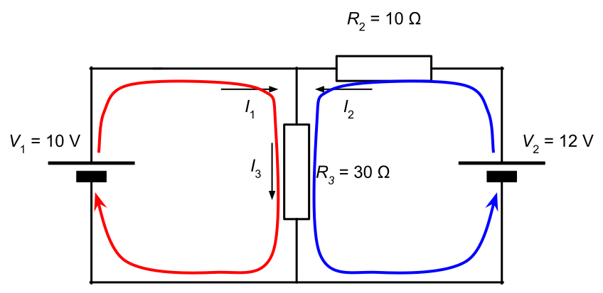
We can see that the red loop has an emf of $\quantity{10}{V}$ so the total p.d. around that loop must also be $\quantity{10}{V}$, as there is only one component in the red loop, it must have a potential difference of $\quantity{10}{V}$ across it.
If we tried to solve this using the blue loop, then the p.d. across $R_{3}$ will be lower than $\quantity{10}{V}$ which means that Kirchhoff’s law is not satisfied for the red loop as well.
As this is a complicated circuit, to answer this question, we have to think carefully about what we already know. We know that the p.d. across $R_{3}$ is $\quantity{10}{V}$, so we can deduce the p.d. across R2 as $\quantity{12}{V}-\quantity{10}{V}=\quantity{2}{V}$. From this we just need to use $R=\frac{V}{I}$ to calculate the current:
In this part of the question we are being asked to not only describe the effect of the changing resistance of one component on the whole circuit but explain why it is happening. Again, by thinking carefully about the ideas we have already looked at we can break this question down into three stages.
Firstly, as the resistance $R_{1}$ increases then the p.d. across the component must also increase, because potential difference is proportional to resistance.
Secondly, the total p.d. around that loop must equal $\quantity{10}{V}$ therefore the p.d. across $R_{3}$ must begin to decrease.
Finally, we can relate the change in the potential difference across $R_{3}$ to the change in potential difference across $R_{2}$. We know that the sum of the potential differences across the two components must equal the emf of that loop, or:
so as the p.d. across $R_{3}$ decreases, the p.d. across $R_{2}$ must begin to increase.