
3.5.1.4 Circuits
Energy and power equations:
The relationships between currents, voltages and resistances in series and parallel circuits, including cells in series and identical cells in parallel.
Conservation of charge and conservation of energy in dc circuits.
Electrical power
We have already learnt that a resistor dissipates electric potential energy as a current passes through it, and this energy is in the form of heat. In fact, if you leave a current flowing through a resistor for a period of time and feel it, it will often be quite warm to the touch due to the electrical energy being converted to heat. This is usually more apparent in components such as filament bulb where the electrical energy is converted into heat and light, and the component can get very hot, but it applies to all resistive components.
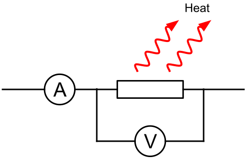
We know that the rate of energy transfer, or the rate of work is called power and is defined as:
Power is always measured in watts ($\units{W}$), where $\quantity{1}{W}$ is $\quantity{1}{J\,s^{-1}}$
We also know that the current flowing through a resistor is the rate of flow of charge, $I=\frac{Q}{t}$ and the potential difference is the work done per unit if charge, $V=\frac{W}{Q}$. These two equations can be rearranged and to make t and W the subjects and substituted into the equation for power to give an expression for the rate of electrical work:
This equation feels very intuitive, the greater the current, the greater the power of the circuit, the greater the p.d. the greater the power. It can be usefully applied to whole circuits, if you know the emf of the cell, or to individual components, if you know the p.d. across that individual component.
It is also worth noting that as power is the rate of work, the total energy supplied is the product of the power and time, which for an electrical circuit can be stated as:
Worked example
The heater in a kettle, designed to operate from the $\quantity{12}{V}$ battery in a car, has a power rating of $\quantity{130}{W}$.
- Calculate the current drawn from the battery by the kettle.
- The energy needed to raise the temperature of two cups of cold water to boiling point is $\quantity{170}{kJ}$.
Calculate the minimum time, in minutes, that it would take to raise the temperature of this water to its boiling point.
We have been given everything that we need in the question., and it is just a matter of rearranging the equation for power given above:
So
Firstly we need to make sure that we convert $\units{kJ}$ into $\units{J}$, so $\quantity{170}{kJ}=\quantity{1.70\times 10^{5}}{J}$. We know that the kettle delivers $\quantity{130}{J\,s^{-1}}$ and we know that $E=Pt$ so the time taken to boil the kettle is:
Common exam mistake
Two unit conversions are hiding in this question: kJ → J (×1000) before using the energy in $P=\frac{E}{t}$, and seconds → minutes (÷60) at the end, since the question specifically asks for the answer in minutes. Missing either conversion is a very easy way to lose marks even when your physics and method are completely correct.
Which we need to state in minutes as $\quantity{21.8}{minutes}$.
Power and resistance
Clearly, as components with a resistance dissipate energy in the form of heat, it would be useful to be able to calculate their power in terms of their resistance.
We can substitute either $V=IR$ or $I=\frac{V}{R}$ into the electrical power equation to produce two equations that link power, resistance, and either current or potential difference:
And
At first glance it may seem that these two equations are contradictory, one says that power is directly proportional to the resistance and the other says that power is inversely proportional to resistance; how can they both be correct?
Common exam mistake
Both equations are always true, but they're only useful once you know what's being held constant. If the p.d. across a component is fixed (e.g. a single resistor across a fixed-emf cell), use $P=\frac{V^{2}}{R}$. If the current through a component is fixed (e.g. resistors sharing a series loop), use $P=I^{2}R$. Picking the equation that matches the fixed quantity in the question avoids the apparent contradiction entirely.
If we consider the circuit below we can see that the potential difference across the resistance R is $\quantity{3.0}{V}$.
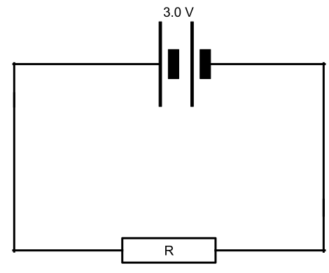
If the value of R decreases then more current will flow through it and as the p.d. will remain constant there will be more energy dissipated each second, therefore the power increases. This gives us the inverse relationship we have in the second equation, $P=\frac{V^{2}}{R}$
However, in this circuit, the two resistors, R1 and R2 start of with the same resistance, and the battery supplies a constant current of I.
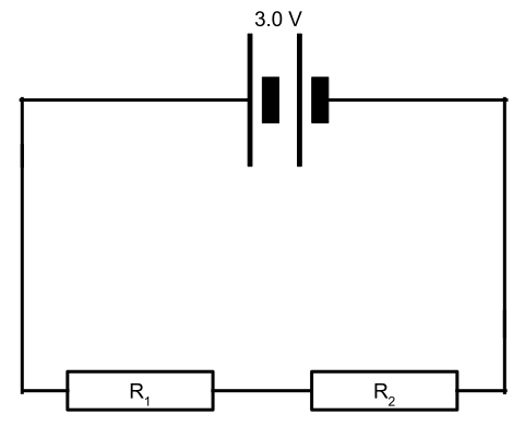
Initially the p.d. across the two resistors is equal, as they have the same resistance, If the value of R2 increases then there will be a greater p.d. across it compared to R1 for the same value of current. Therefore, as the p.d. is greater the power dissipated is also greater for an increased resistance. This is clearly the directly proportional relationship seen in $P=I^{2}R$.
The power dissipated by resistors is in the form of heat, and this can be usefully harnessed in heaters, such as kettles and other heating elements, such as those in car windscreens, or electric cookers. These will generally have high resistance, as part of a circuit, so that there is a large p.d. across the element. If the resistor was placed across the power supply alone, with a very low value, the high current draw could melt a fuse or create a short circuit, damaging the electric supply.
Cells in series and parallel
It is possible to combine multiple cells together in a circuit to produce a battery. The properties of the battery depend on how the cells are connected together.
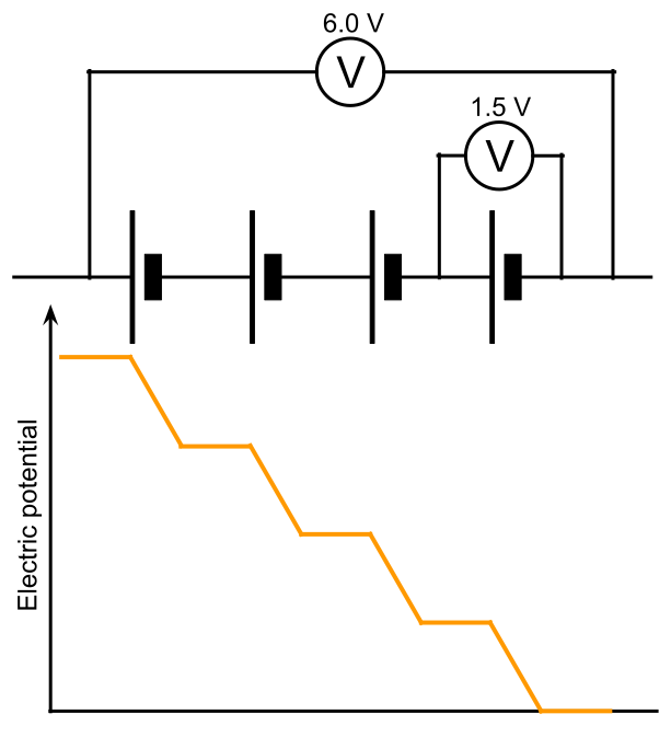
If the cells are connected in series, the charges will gain electrical potential each time they pass through a cell. So the total emf of several cells in series is the sum of the individual emfs of each cell. In this case, as the charges are all flowing through the same series circuit, the current in the circuit is the same as it would have been for one cell
When cells are arranged in parallel, the charges each pass through one cell only, so they only gain electric potential in one cell, therefore the emf of the circuit is equal to the individual emf of any of the cells (assuming that they are all the same value). However, as each cell is delivering charge to the circuit, the current supplied to that circuit will be the sum of the individual currents supplied.
Common exam mistake
The "parallel cells share the current, emf stays the same" rule only applies to identical cells connected the same way round. Don't apply it to cells with different emfs — mismatched cells in parallel isn't something the spec asks you to calculate, and assuming it behaves like the identical-cell case is a common overreach in exam answers.
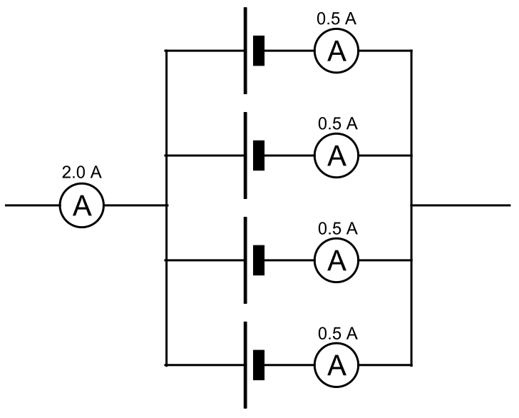
Very large currents can be produced by arranging several cells in parallel, and arranging them in parallel can also increase the capacity in $\units{mAh}$
Conservation of energy in circuits
When a cell converts chemical energy into electrical potential it does so at a rate of $P=IV$. The energy delivered by the cell is transferred by the resistances of the components and the wires as heat, light or other useful work. Electrical circuits are, of course, subject to the law of the conservation of energy, so every single joule of energy the cells converts needs to be used around the circuit. We can demonstrate this by looking at the power delivered by a cell and then comparing it to the power being transferred by the resistors within the circuit.
In the circuit below the energy being transferred by the cell is turned into light and heat by the bulb and heat by the two resistors.
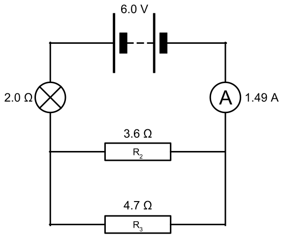
The emf of the cell is $\quantity{6.0}{V}$, and it it delivering $\quantity{1.49}{A}$ of current. The power being delivered to the whole circuit is:
We know that the current flowing through the bulb is $\quantity{1.49}{A}$, so the power it is transferring is:
To easiest way find the power being transferred by the two parallel resistors is to find the potential difference across the the two resistors. This will be the difference between the emf of the cell and the p.d. across the bulb.
Common exam mistake
It's tempting to reuse the $\quantity{1.49}{A}$ total current for the parallel resistors too — but that current only flows through the bulb. Each parallel branch has its own current and its own share of the p.d.; you need to work those out separately (as below) rather than reusing values from a different part of the circuit.
The p.d. across the bulb is:
So the potential difference across the parallel resistors will be:
We can now calculate the power of each of the two parallel resistors,
- R2
- R3
If we add the power developed by each resistor we can see that it is equal to the power being transferred by the cell and thus confirm that energy has been conserved in the circuit:
Power delivered by the cell = power developed by resistors
Worked example
The diagram below shows the circuit for a small convector heater. Heater elements can be switched in and out of the circuit using switches X and Y. Each element has a resistance R and the power supply has an emf V.

- The table shows the possible combinations of open and closed switches. When a switch is closed, charge can flow through it.
Complete the table. Assume that the internal resistance of the power supply is negligible. The first row of the table has been done for you. - For the first row when X is open and Y is closed, the current only flows through one resistor as switch Y acts like a short circuit around one of the resistors, so the total value of the circuit’s resistance is R.
- When X is closed and Y is open the current flows through all of the resistors. As the resistances are all given as R, our answer must be in terms of R, and as there is no data in the question, we must work algebraically.
- The third row shows the switches as X open and Y open. In this case the current only flows through the two resistors in the bottom branch, and none flows through the top resistor. Therefore the total resistance of the circuit is $\large 2R$.
- The final row of the table shows the switches as X closed Y closed. Now the current is flowing through the top resistor and only one of the bottom resistors. The two branches of the parallel network have the same resistance so we can state that as:
- State and explain which switch combination will dissipate least energy.
| switch combination | total resistance in circuit |
|---|---|
| X open, Y closed | R |
| X closed, Y open | |
| X open, Y open | |
| X closed, Y closed |
Using the equation for resistors in parallel we get:
We can now add the two fractions that are on the right hand side of the equation, for which the step by step solution goes:
We need to make both of the denominators the same, so we double the first term as $\frac{1}{R}=\frac{2}{2R}$:
We now add the two numerators $\left(2+1=3\right)$ and place the result over the common denominator:
However, as this equals $\frac{1}{R_{T}}$ we need to find the reciprocal of $\frac{3}{2R}$ which simply involves flipping the fraction, so the total value for the resistance of the circuit for the second row is:
If you know how to add fractions well, or can see other short-cuts, then there is no need to do all of this working, but I am showing it here for clarity.
Again adding the two fractions on the right hand side we get:
Finally flipping the fraction to find RT:
So our final table will look like this:
| switch combination | total resistance in circuit |
|---|---|
| X open, Y closed | R |
| X closed, Y open | $\frac{2R}{3}$ |
| X open, Y open | $2R$ |
| X closed, Y closed | $\frac{R}{2}$ |
Common exam mistake
With four different resistance values but the same emf across all of them, use $P=\frac{V^{2}}{R}$ to compare — not $P=I^{2}R$, since the current is different in each case and hasn't been calculated. Students who instinctively reach for $P=I^{2}R$ here end up needing an extra unnecessary step to find each current first.
For each combination of switches, the total potential difference across the circuit is the same, V. Therefore we can consider each of the combinations in terms of $P=\frac{V^{2}}{R}$. As this is an inverse relationship the largest value for the total resistance of the circuit will have the least power, and therefore dissipates the least energy. The largest value for total resistance is when X is open and Y is open, so this will dissipate the least energy.
Test yourself
Try the questions below to check your understanding of this topic. Numerical questions use different numbers each time, so you can attempt them more than once.